Hydraulic Press

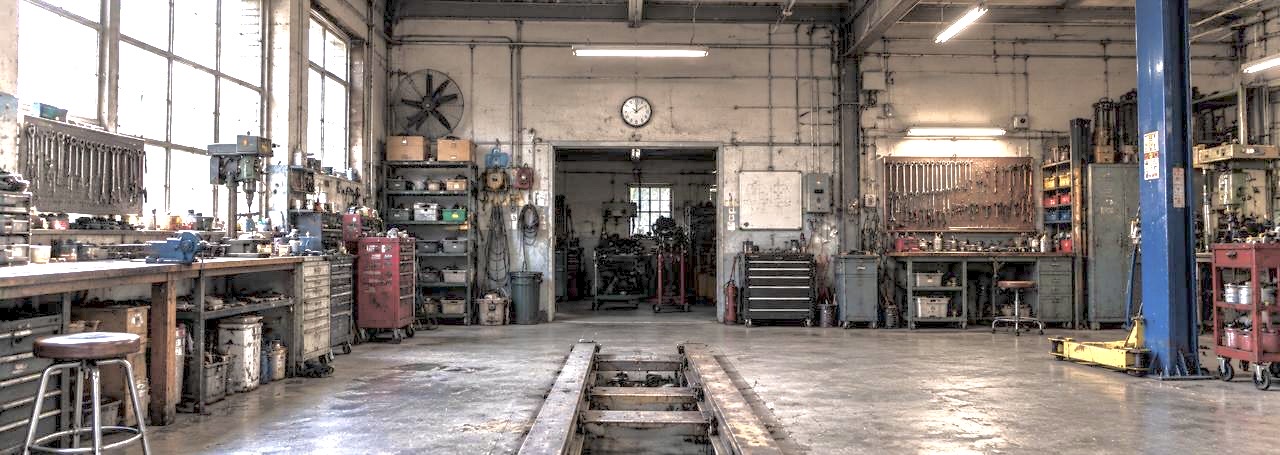
- The department planned to automate a hydraulic press already available in its lab
- This involved studying the machine’s design, components and assembly
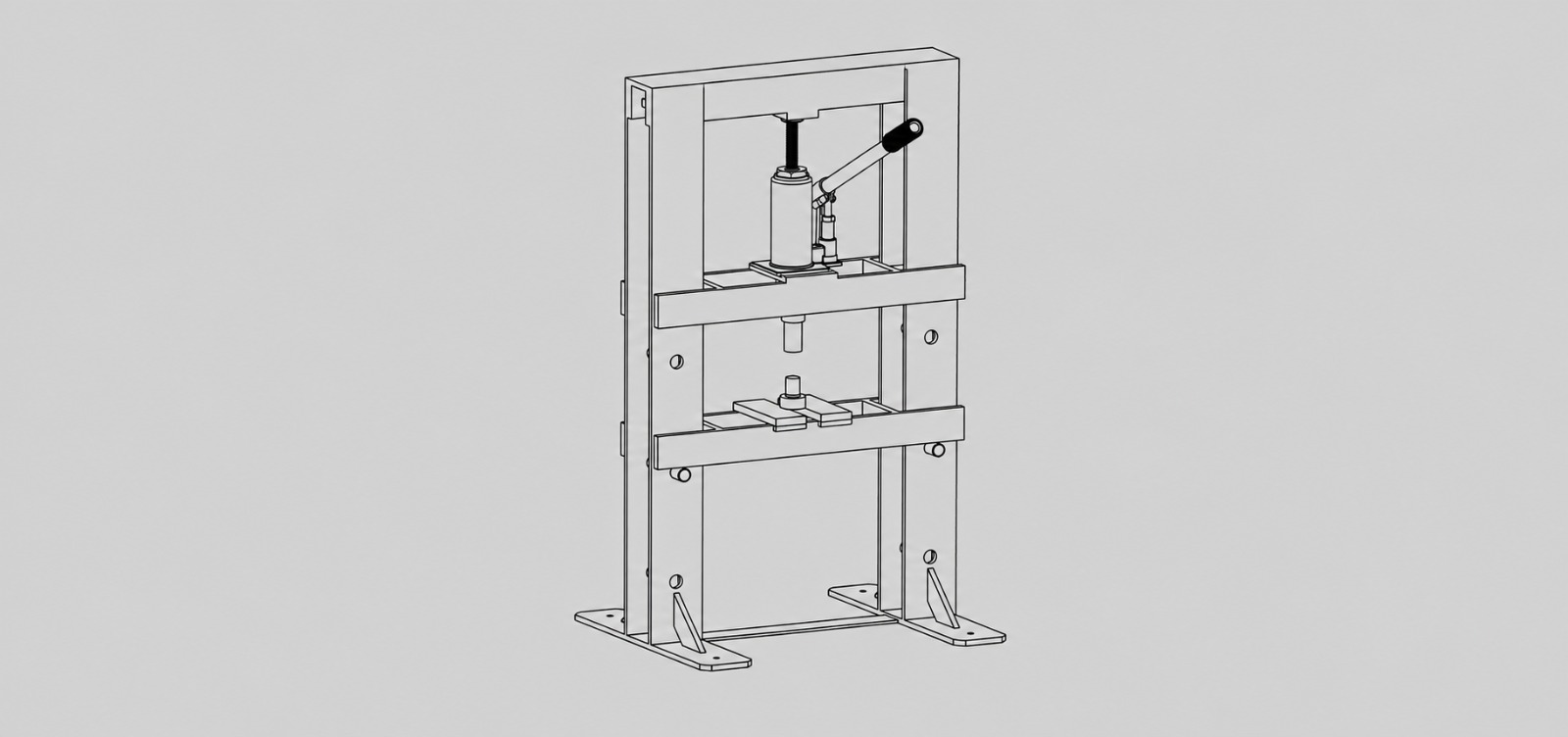
- Designed a hydraulic press
- CAD modelling individual components and assembling them into a complete system

- Evaluated the structural integrity of the working bed using FEA, with a maximum von Mises stress of 65 MPa.
- Maximum deformation was 0.117 mm under the analysed loading conditions.
Studying the hydraulic press, its components and how they fit together.
Modelling individual components, assembling them into a complete system and sing FEA to evaluate the working bed under the applied loading conditions.
The Assembly
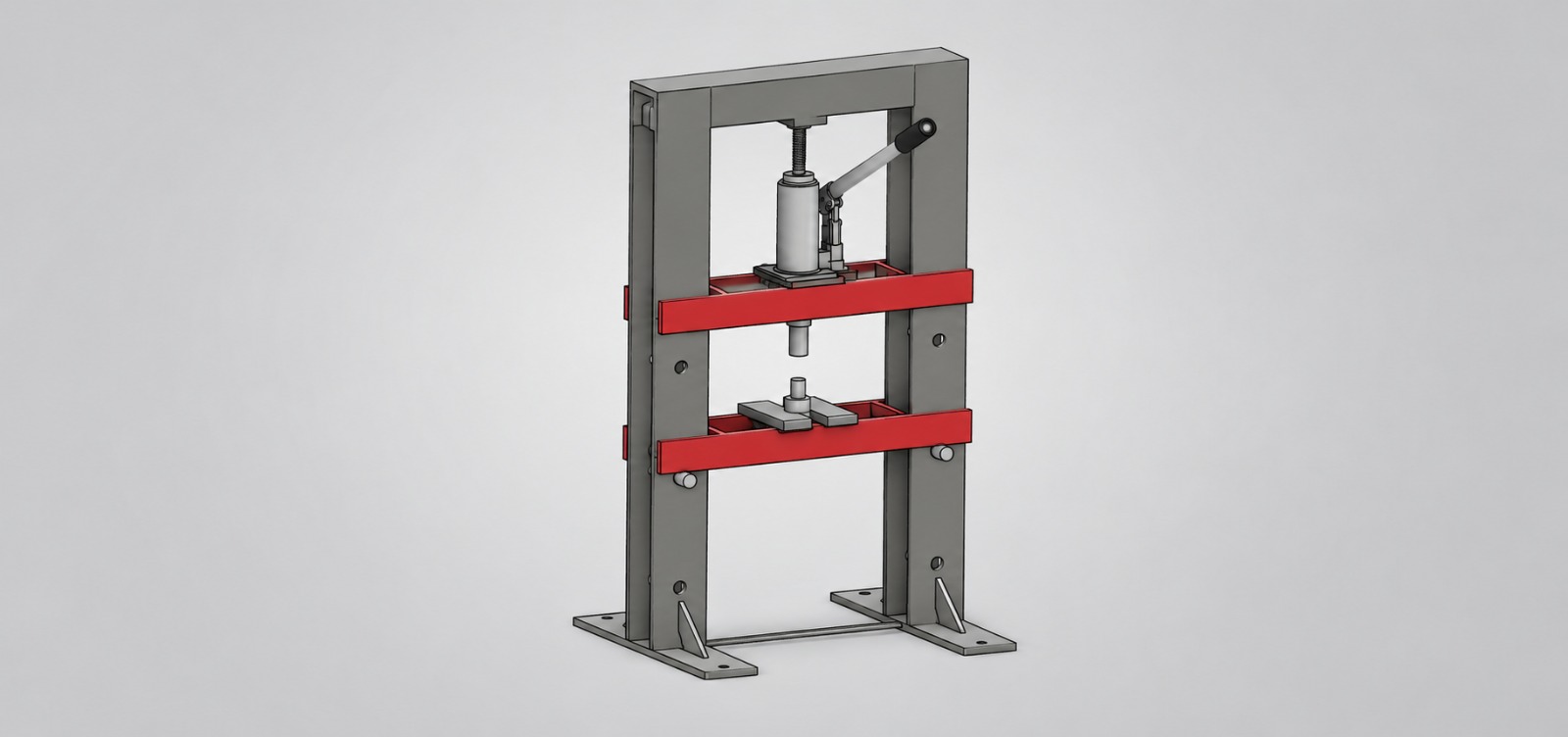
Component Breakdown
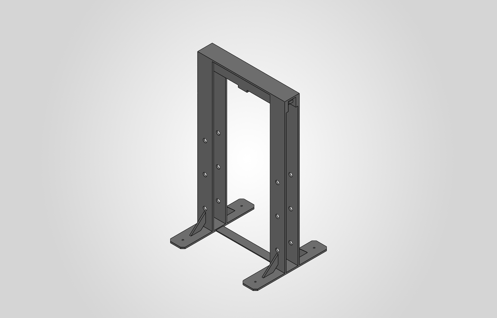
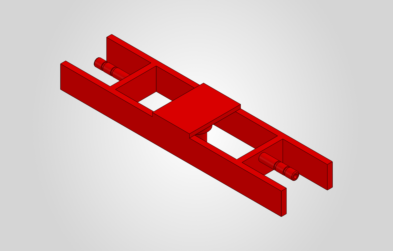
H-Frame
Provides the main structural support and withstands the loads generated during pressing
Material: Mild steel
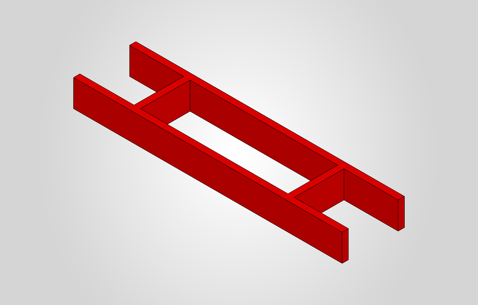
Upper Beam
Supports the upper part of the press assembly and transfers loads to the frame
Material: Mild steel
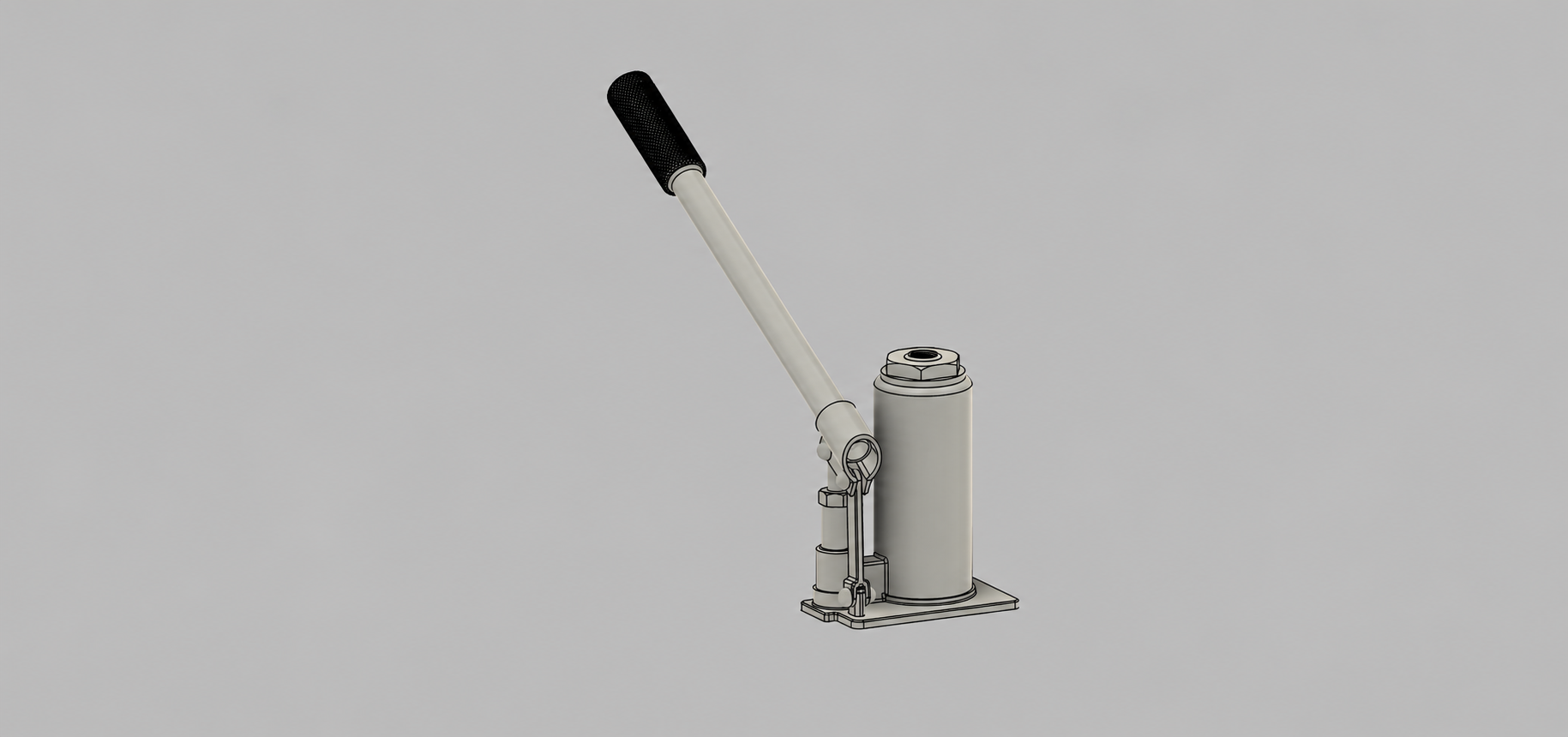
Lower Beam
Supports the workpiece and provides a rigid base for the pressing operation
Material: Mild steel
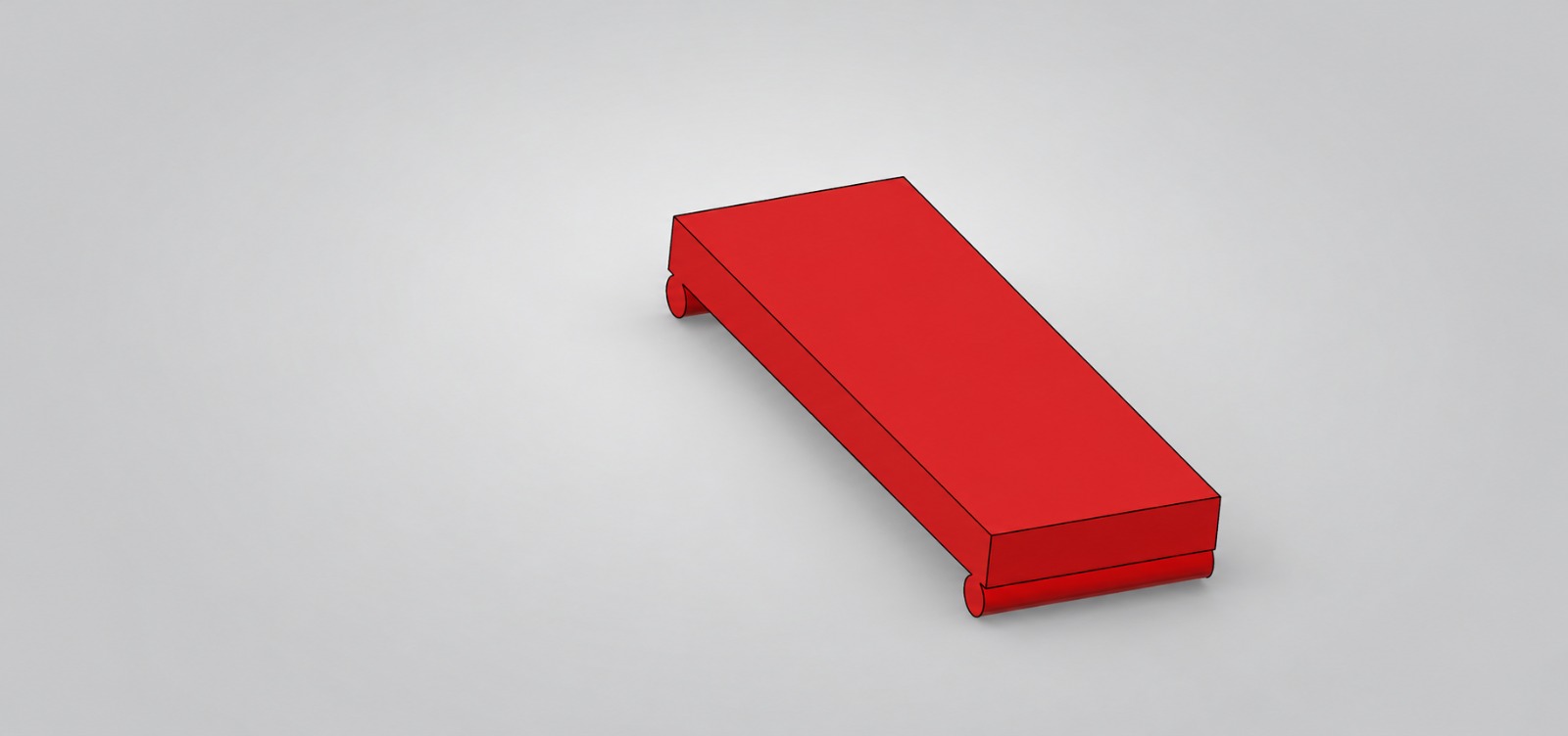
Piston
Converts hydraulic pressure into linear motion to generate the pressing force
Material: Steel
Beam Base
Provides a flat supporting surface for positioning the workpiece during pressing
Material: Mild steel
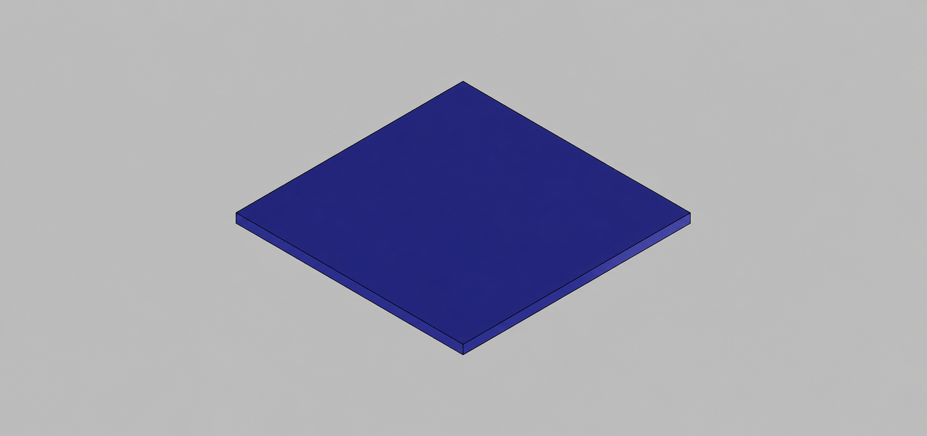
Base
Supports and locates the hydraulic mechanism within the press assembly
Material: Mild steel
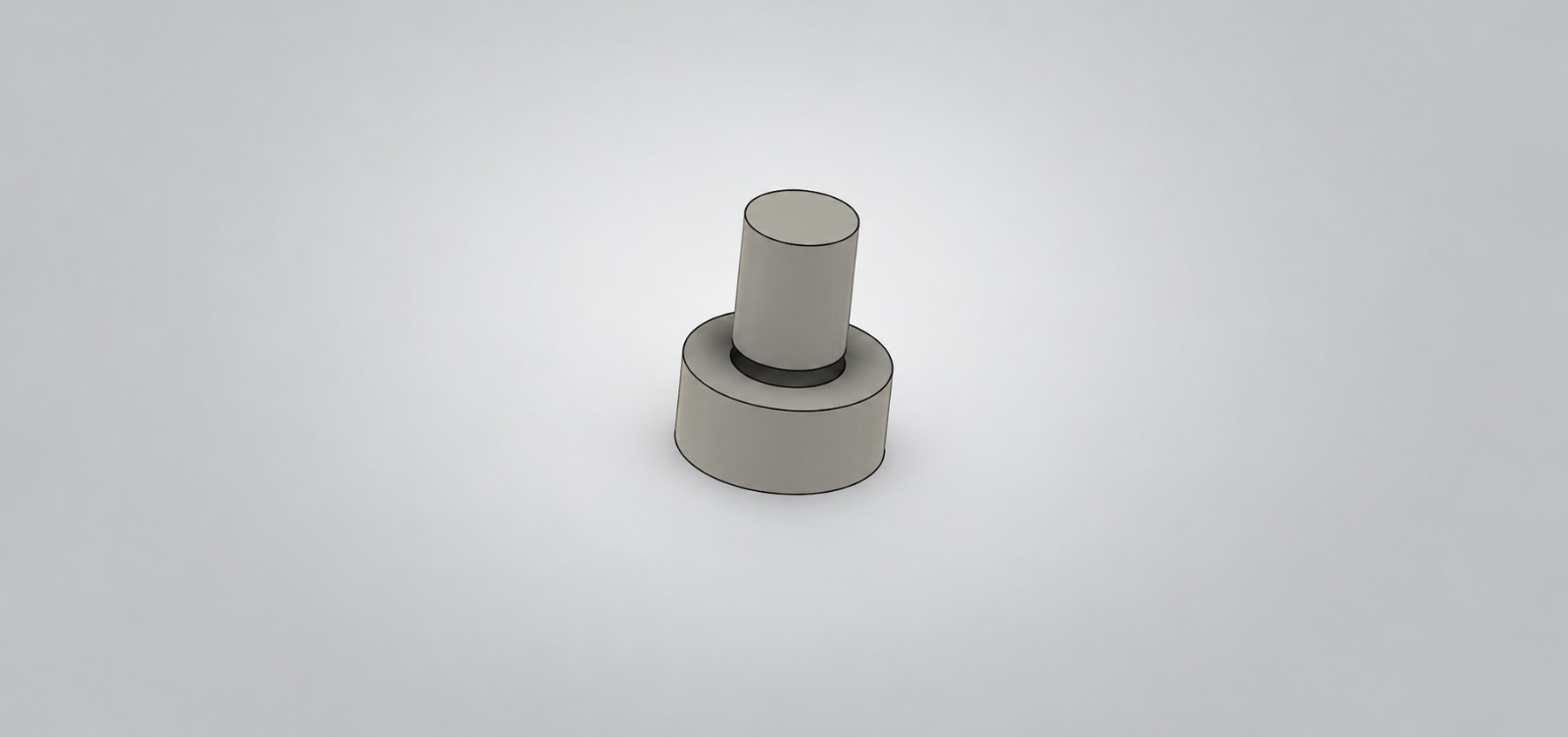
Work Piece
Represents the component positioned beneath the punch for the pressing operation
Material: Mild steel
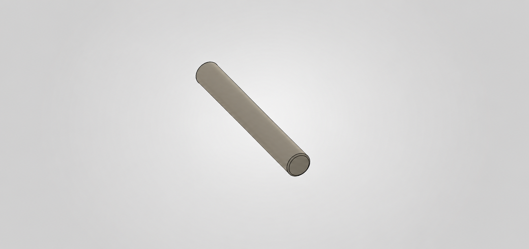
Fastener
Secures the assembled components and helps maintain structural alignment
Material: Steel
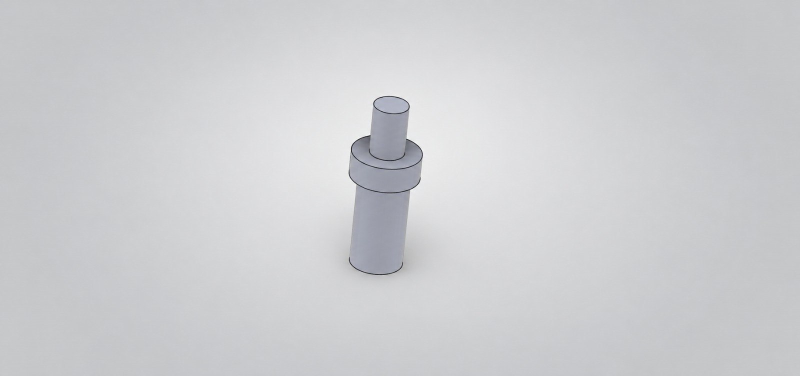
Punch
Applies concentrated force to the workpiece to perform the intended pressing or forming operation
Material: Hardened tool steel